Datei:Dipole antenna standing waves animation 1-10fps.gif
Es ist keine höhere Auflösung vorhanden.
Dipole_antenna_standing_waves_animation_1-10fps.gif (682 × 311 Pixel, Dateigröße: 170 KB, MIME-Typ: image/gif, Endlosschleife, 20 Bilder, 2,0 s)

Beschreibung
| Beschreibung |
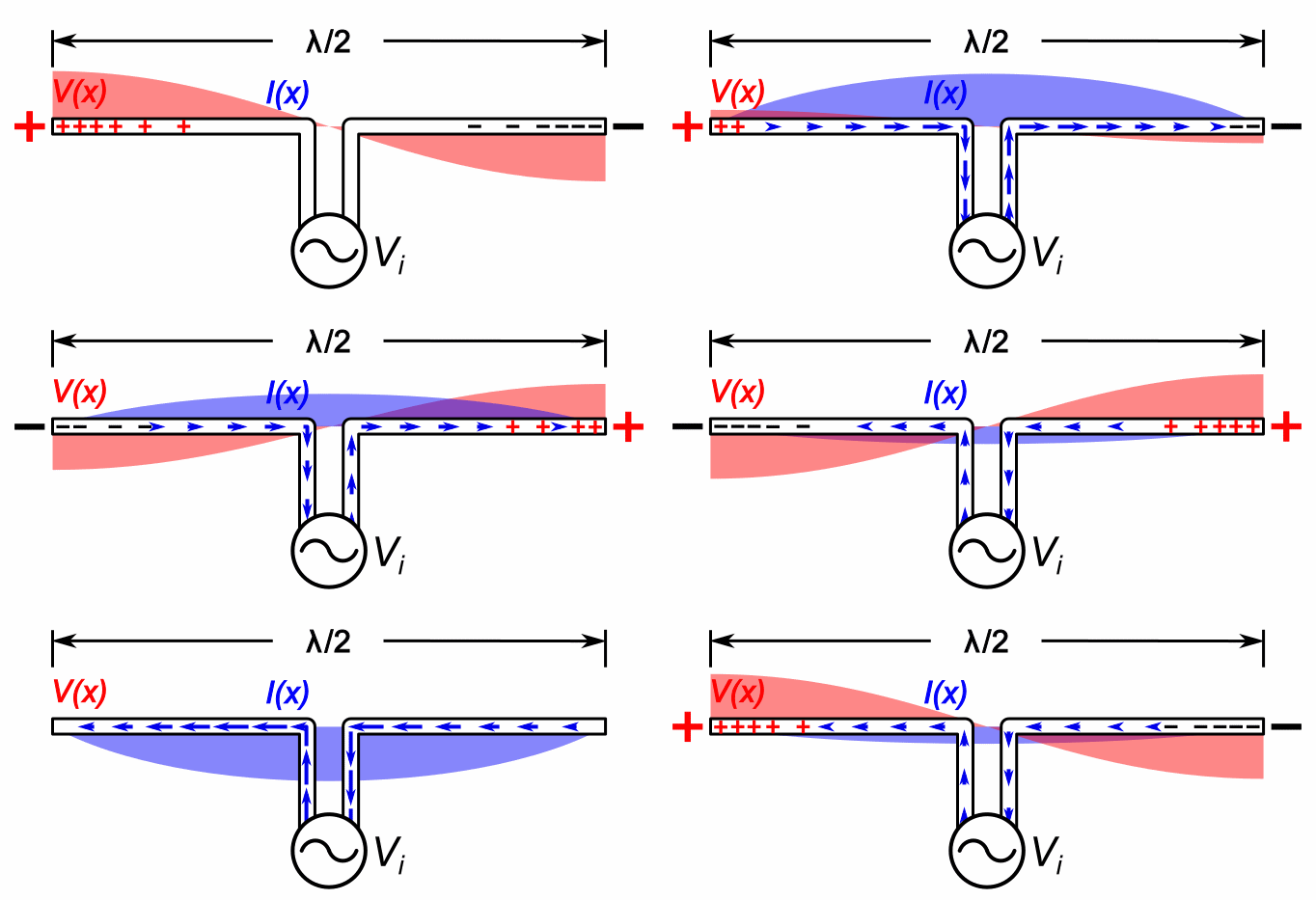
English: Animation showing standing waves on a half-wave dipole antenna driven by a sinusoidal voltage VO from a radio transmitter at its resonant frequency. The oscillating voltage pushes the electrons back and forth along the two metal rods that make up the antenna, creating oscillating currents (blue arrows) in the antenna, charging its ends alternately positive (+) and negative (-). Since at this frequency the antenna is a half wavelength (λ/2) long, a sinusoidal wave of voltage or current takes exactly one cycle to make the round trip from one end of the antenna to the other and back, so the reflected waves reinforce each other. The antenna acts like an electronic resonater. Waves of current and voltage reflecting back and forth between the ends of the rods interfere to form standing waves. The standing waves are shown graphically by bars of color (red for voltage V(x) and blue for current I(x)) whose width at each point is proportional to the amplitude of the wave at that point. There are voltage antinodes (maxima) and current nodes (zero points) at each end, where positive (+) and negative (−) charges accumulate alternately each half cycle, while there is a voltage node and current antinode at the drive point in the center. The large oscillating voltages and currents on the antenna at resonance causes it to radiate maximum radio wave power. The zero voltage reference for the voltage waves, as is customary in these graphs, is halfway between the voltage on the two transmission line conductors. The blue arrows show the direction of conventional current, flow of positive charge; the direction of flow of the electrons in the antenna is opposite to the arrows. The oscillations are shown slowed down enormously; the current in actual radio antennas oscillates back and forth between ten thousand and one billion cycles per second. |
| Datum | |
| Quelle | Eigenes Werk |
| Urheber | Chetvorno |

|
Dieses circuit Bild sollten als spezielle Vektorgrafik als eine SVG-Datei neu angelegt werden. Das hat mehrere Vorteile; siehe Commons:Media for cleanup für mehr Informationen. Wenn eine SVG-Variante dieses Bildes vorhanden ist, lade es bitte hoch und ersetze anschließend diese Vorlage durch
{{vector version available|new image name}}.
Es wird empfohlen, die SVG-Datei wie folgt zu benennen „Dipole antenna standing waves animation 1-10fps.svg“ – dann braucht die Vorlage Vector version available (oder Vva) den new image name-Parameter nicht. |
Lizenz
Ich, der Urheber dieses Werkes, veröffentliche es unter der folgenden Lizenz:
 
|
Diese Datei wird unter der Creative-Commons-Lizenz CC0 1.0 Verzicht auf das Copyright zur Verfügung gestellt. |
| Die Person, die das Werk mit diesem Dokument verbunden hat, übergibt dieses weltweit der Gemeinfreiheit, indem sie alle Urheberrechte und damit verbundenen weiteren Rechte – im Rahmen der jeweils geltenden gesetzlichen Bestimmungen – aufgibt. Das Werk kann – selbst für kommerzielle Zwecke – kopiert, modifiziert und weiterverteilt werden, ohne hierfür um Erlaubnis bitten zu müssen.
|
Dateiversionen
Klicke auf einen Zeitpunkt, um diese Version zu laden.
| Version vom | Vorschaubild | Maße | Benutzer | Kommentar | |
|---|---|---|---|---|---|
| aktuell | 07:00, 9. Jul. 2020 | | 682 × 311 (170 KB) | wikimediacommons>Chetvorno | Improved current arrows, made motion less jerky, added plus and minus charges in antenna |
Dateiverwendung
Die folgende Seite verwendet diese Datei:
